20+ rf tuner block diagram
A single-side PCB for the RF signal detector is shown in Fig. EXPLANATION OF THE RF AND MICROWAVE DEVICES Explain the devices by the microwave block diagram for following application systems.
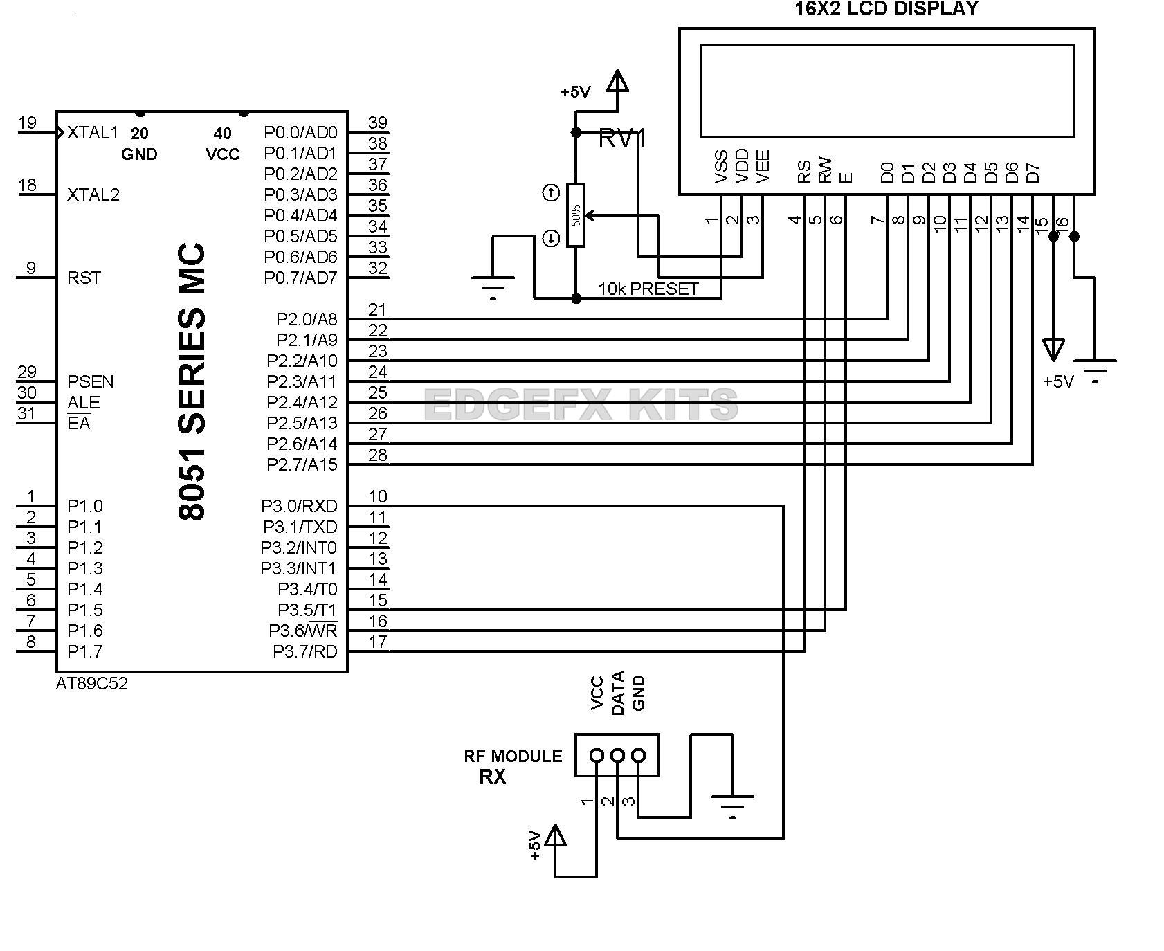
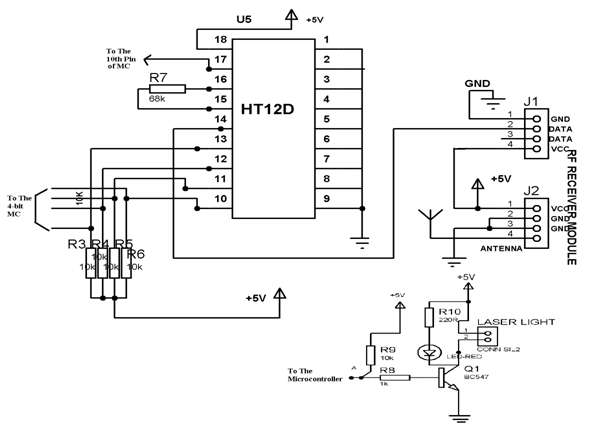
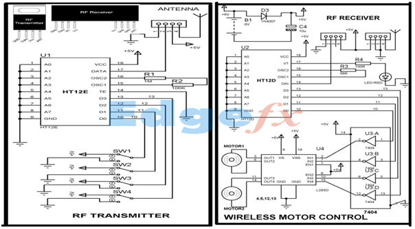
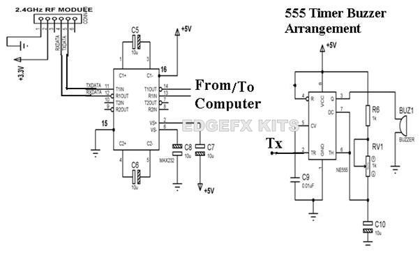
Wireless Rf Module Rf Transmitter And Receiver Latest Applications
Figure 5-3 Timing Card Block Diagram 504.

. About TDA7000 FM Receiver TV Tuner. The tuner chip is an analog downconverter from VHFUHF to frequencies of a few MHz which can be handled by the RTL chips AD converters. Here weve lumped the Tx and Rx sides together using an.
PAL decoder provides RGB signals. RF Transceiver Block Diagram RF modules can be applied for various types sizes and shapes of electronic circuit boards. Mobile Communication System Digital.
The RF signal generator is a must to have tool when playing with radio receivers. It is 50 ohms. Two kinds of tuner chips Figure a shows the.
Point B is the antenna tuners to transceiver port which is also 50 ohms. FM tuners audible quality largely depends on the lnearity of its FM detec-tor. Unmatchable RF performance for all digital broadcast television standards including DVB-T ATSC DMB-T ISDB-T.
2 and its component layout in Fig. This Magnetic Loop Tuner - a Concept and Overview As was previously mentioned the magnetic loop consists of an inductive loop connected to a variable capacitor. The functional block diagram below shows the general topology of an RF front end.
Assemble the circuit on a PCB to minimize time and assembly errors. Functional Block Diagram Figure D. PLL Divider 7 Tuner PLL 8 IFAmplifier FM Demodulator 9 Squelch Logic.
There are 187 circuit schematics available in this category. Block Diagram 3 Programmer Data 4 Programmer Control 5 Readout Preload Decoder 6 Reference Osc. Block diagram and pin description TDA7706 816 Doc ID 022898 Rev 3 52 OSCin In Oscillator Crystal oscilllator input - 53 OSCout Out Crsystal oscillator output 54 GND-REF - - Front-end.
It consist of colour demodulator which provides demodulated U and V signals. It can also be useful for modules across a vast variety. Sensitivity is gained by distributing the conversion.
PAL Decoder Color Processing section. The Timing Card converts the 10 MHz frequency standard into the 16 MHz sys- tem reference frequency and generates the 20. The fm tuner circuit is.
Point A is the transceiver antenna port. RF Transceiver consists of RF Up converter RF down converter. This sensitive FM radio tuner is the right circuit for hobbyists who want to build their own tuners instead of buying a plug-n-play finished product.
This triple conversion receiver is typical of many designs past and present. Thank you for purchasing. It is used to tune a resonant circuits and adjust the gain of different RF stages.
The Last circuit was added on Saturday August 21 2021Please note some adblockers will. The L-OlT has employed n its detector a Pulse Count system which has essentially a lnear response over the. This page on C band RF transceiver design and development describes various modules as per RF transceiver block diagram.
Two trusted TIC contributors vouch for his work. The block diagram of the super-het receiver is shown above. Foster Blair rebuilds and repairs all types.
Consider the diagram below. Very useful feature of the RF. The circuit designs of the capacitive attenuator type RF VGA the fast-locking fractional-N PLL and other building blocks are described and measured results are also presented.
Use Createlys easy online diagram editor to edit this diagram collaborate with others and export results to multiple image formats. Click here for all circuit diagrams.

Simplified Block Diagram Of The Global Car Radio Tuner Ic Download Scientific Diagram

Block Diagram Of The Designed Rf Tuner Download Scientific Diagram

Adi S Rf Front End Family Enables Compact 5g Massive Mimo Network Radios Analog Devices
Wireless Rf Module Rf Transmitter And Receiver Latest Applications

7 Radio Frequency Circuit Diagrams Eleccircuit Com Radio Frequency Circuit Circuit Diagram
![]()
Wireless Rf Module Rf Transmitter And Receiver Latest Applications

Block Diagram Of Rf Tuner Download Scientific Diagram

Block Diagram Of The Designed Rf Tuner Download Scientific Diagram

7 Radio Frequency Circuit Diagrams Eleccircuit Com Radio Frequency Circuit Circuit Diagram

Adi S Rf Front End Family Enables Compact 5g Massive Mimo Network Radios Analog Devices
What Made The Tuned Radio Frequency Receiver Circuit Different From The Simple Radio Receiver Circuit Quora
Wireless Rf Module Rf Transmitter And Receiver Latest Applications
![]()
Wireless Rf Module Rf Transmitter And Receiver Latest Applications

Block Diagram Of Rf Front End For Terrestrial Dtv Tuner Download Scientific Diagram
Wireless Rf Module Rf Transmitter And Receiver Latest Applications

Block Diagram Of Rf Tuner Download Scientific Diagram

Block Diagram Of Rf Tuner Download Scientific Diagram